
| Orig. Posting Date | User Name | Edit Date |
| May 24, 2018 12:39PM | Bullet18 | |
| May 24, 2018 11:19AM | Bullet18 | |
| May 24, 2018 11:14AM | Bullet18 | |
| May 23, 2018 01:55PM | mur | |
| May 23, 2018 09:58AM | Bullet18 | |
| May 23, 2018 09:46AM | Bullet18 | |
| May 16, 2018 11:43AM | malsal | |
| May 16, 2018 08:18AM | dklawson | |
| May 16, 2018 05:43AM | Bullet18 | Edited: May 16, 2018 06:21AM |
| May 16, 2018 05:31AM | mur | |
| May 16, 2018 03:59AM | dklawson | Edited: May 16, 2018 04:07AM |
| May 16, 2018 03:51AM | MiniCord | |
| May 15, 2018 03:14PM | malsal | Edited: May 15, 2018 03:19PM |
| May 15, 2018 02:16PM | Dan Moffet | |
| May 15, 2018 12:17PM | Bullet18 | |
| May 15, 2018 09:49AM | Bullet18 | |
| May 15, 2018 09:39AM | onetim | |
| May 15, 2018 09:38AM | Bullet18 | |
| May 15, 2018 09:06AM | Bullet18 | |
| May 15, 2018 08:53AM | Bullet18 |

|
Total posts: 47
Last post: Aug 20, 2022 Member since:May 14, 2018
|
Cars in Garage: 0
Photos: 0 WorkBench Posts: 0 |
 I put the flasher on from my challenger and it fixed the issue. if only all my challenger parts fit. Thanks for the help.
|
|
Total posts: 47
Last post: Aug 20, 2022 Member since:May 14, 2018
|
Cars in Garage: 0
Photos: 0 WorkBench Posts: 0 |
|
|
Total posts: 47
Last post: Aug 20, 2022 Member since:May 14, 2018
|
Cars in Garage: 0
Photos: 0 WorkBench Posts: 0 |
|
|
Total posts: 5840
Last post: Nov 1, 2019 Member since:Nov 12, 1999
|
Cars in Garage: 0
Photos: 0 WorkBench Posts: 0 |
|
You checked all that?
and it is all good?
|
|
Total posts: 47
Last post: Aug 20, 2022 Member since:May 14, 2018
|
Cars in Garage: 0
Photos: 0 WorkBench Posts: 0 |
 I got it out and nothing seems to be wrong. Any ideas?
|
|
Total posts: 47
Last post: Aug 20, 2022 Member since:May 14, 2018
|
Cars in Garage: 0
Photos: 0 WorkBench Posts: 0 |
|
|
Total posts: 8382
Last post: Jan 13, 2022 Member since:Feb 7, 2006
|
Cars in Garage: 0
Photos: 0 WorkBench Posts: 0 |
|
If in doubt, flat out. Colin Mc Rae MBE 1968-2007.
Give a car more power and it goes faster on the straights,
make a car lighter and it's faster everywhere. Colin Chapman.
|
|
Total posts: 9241
Last post: Aug 17, 2023 Member since:Jun 5, 2000
|
Cars in Garage: 0
Photos: 0 WorkBench Posts: 0 |
|
|
|
Total posts: 47
Last post: Aug 20, 2022 Member since:May 14, 2018
|
Cars in Garage: 0
Photos: 0 WorkBench Posts: 0 |
|
|
Total posts: 5840
Last post: Nov 1, 2019 Member since:Nov 12, 1999
|
Cars in Garage: 0
Photos: 0 WorkBench Posts: 0 |
|
https://www.minimania.com/images/wiring/PDFs/wiring10.pdf
This is far far easier to read. I think the later cars tended towards the hazard switch before the flasher.
This fellow already says he has a Haynes that covers his car. He will have a correct diagram on hand.
Ultimately he will need to get a test lamp and check things. As the Blue Potatoe fellow put it recently, it is always the Hazards switch....
|
|
Total posts: 9241
Last post: Aug 17, 2023 Member since:Jun 5, 2000
|
Cars in Garage: 0
Photos: 0 WorkBench Posts: 0 |
|
See the schematic in the link below. It's for a 1275 GT with rocker switches. It will be very representative of most 1970s Minis.
https://www.minimania.com/images/wiring/PDFs/wiring13.pdf
Towards the bottom right corner of the diagram find items 25, 26, 153, and 154. Those items are the turn signal flasher, the turn signal switch, the hazard switch and the hazard flasher. Note that some of the wires are shown dashed (optional or not in all applications). Try troubleshooting using this diagram. At the bottom of sheet 2 of the diagram you will find the wiring color code key. The color codes did not change over the years for the Mini or other British cars. It's a standard. Once you can troubleshoot one British car's wiring... you can work on almost any of them.
As I mentioned before, spend some time with the wiring diagram and a multimeter looking for where the turn signal circuit loses power. You will see that the schematic shows the turn signal circuit using a 2 wire flasher while the hazard switch uses a 3 wire flasher. The turn signals are powered by a dark green wire. Dark green wires are switched AND fused. Start your troubleshooting by turning the key to the run position and checking for power on the 2 pin flasher terminal with the dark green wire. From there, check for power on the second flasher terminal with the light-green/brown (LGN) wire. If you still have power, go to the hazard switch. Look for voltage on BOTH of the light-green/brown wires attached to the hazard switch.
Remember the turn signal troubleshooting should be done with the key in the run position. Let us know what you find.
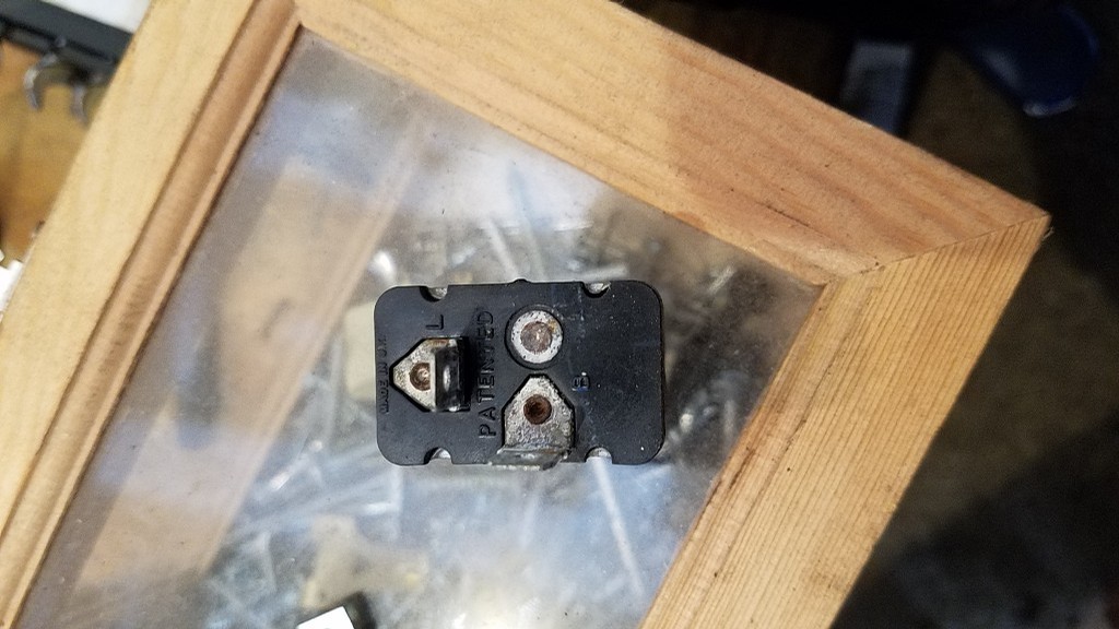
Footnote on flasher terminals. Power in is supplied on the "B" (battery) or "X" terminal. The "L" terminal is the LOAD (lights). When a third terminal is present, it is typically labeled "P"
EDIT: Sorry. I forgot to mention that the flasher you posted a picture of (9FL) is a 2 pin flasher. Don't bother looking for a missing third wire.
|
|
Total posts: 1179
Last post: Jan 22, 2021 Member since:Jul 31, 2008
|
Cars in Garage: 5
Photos: 107 WorkBench Posts: 3 |
|
If your flashers work, but not the turn signals.
Fuses
The flasher unit below the dash is for turn signals, the hazard lights one is under the hood, which you found.
Check the hazard light switch, it is a two way switch when the flashers are off the switch closes to allow turn signals, it opens when the flashers are on. If its worn or there is a bad contact, it will not let you use the turn signals.
Finally, the turn signal stalk.
Good luck!

|
|
Total posts: 8382
Last post: Jan 13, 2022 Member since:Feb 7, 2006
|
Cars in Garage: 0
Photos: 0 WorkBench Posts: 0 |
|
The fuse box looks fine but the cover is missing.
You need to start by seeing if you have power to the stalk and or the flasher relay with a test light or multi meter and go forward or backwards from there until you find the break.
Doug posted wiring diagrams on this thread.
If in doubt, flat out. Colin Mc Rae MBE 1968-2007.
Give a car more power and it goes faster on the straights,
make a car lighter and it's faster everywhere. Colin Chapman.
|
|
Total posts: 9545
Last post: Apr 25, 2024 Member since:Aug 14, 2002
|
Cars in Garage: 0
Photos: 0 WorkBench Posts: 0 |
|
Wiring diagrams are available in the Haynes manuals - you want the "1969 to Oct 1996" version. Most likely "Wiring Diagram 18 - 1988-on carburettor models. Note the diagrams can be cryptic and it is sometimes useful to study earlier diagrams to understand the various systems as later ones are variants of earlier ones, until you get to fuel injections versions.
.
"Hang on a minute lads....I've got a great idea."
|
|
Total posts: 47
Last post: Aug 20, 2022 Member since:May 14, 2018
|
Cars in Garage: 0
Photos: 0 WorkBench Posts: 0 |
|
|
Total posts: 47
Last post: Aug 20, 2022 Member since:May 14, 2018
|
Cars in Garage: 0
Photos: 0 WorkBench Posts: 0 |
|
|
Total posts: 1007
Last post: Jul 19, 2022 Member since:Jul 24, 2014
|
Cars in Garage: 0
Photos: 0 WorkBench Posts: 0 |
|
|
Total posts: 47
Last post: Aug 20, 2022 Member since:May 14, 2018
|
Cars in Garage: 0
Photos: 0 WorkBench Posts: 0 |
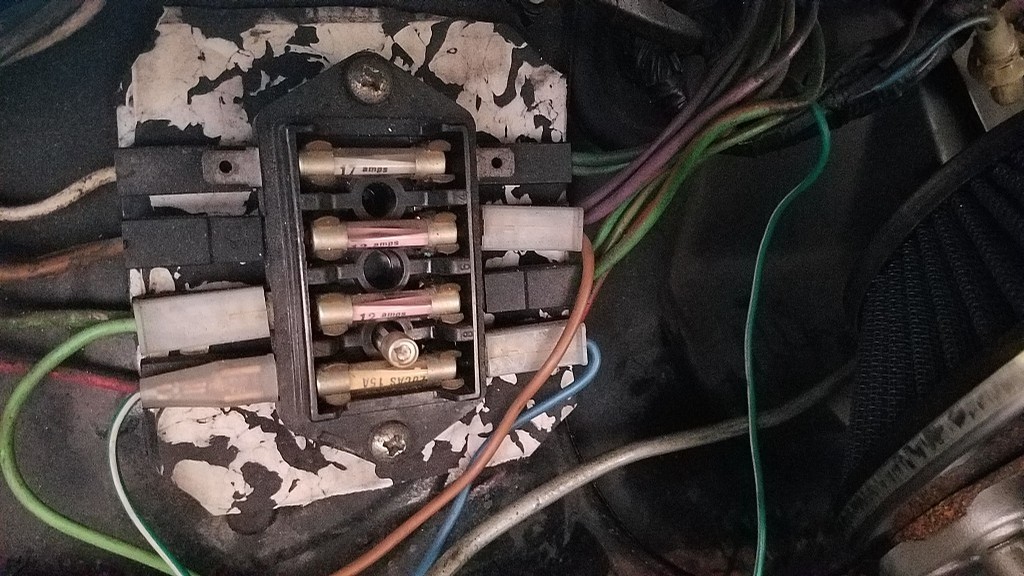 Does anything look wrong with the fuse box? There are 2 leads missing from both the front top corners and some of the fuses are pink.
|
|
Total posts: 47
Last post: Aug 20, 2022 Member since:May 14, 2018
|
Cars in Garage: 0
Photos: 0 WorkBench Posts: 0 |
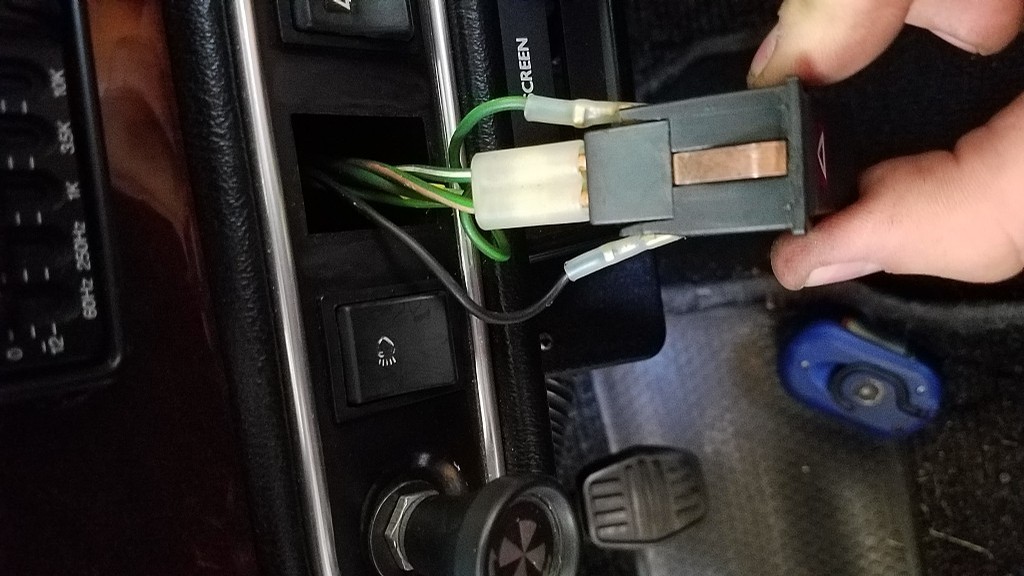
 There was no connection to the circle with no tab. Honestly i dont know if theres supposed to be but there is a place for a wire on the plastic bracket it mounts in.
|
|
Total posts: 47
Last post: Aug 20, 2022 Member since:May 14, 2018
|
Cars in Garage: 0
Photos: 0 WorkBench Posts: 0 |
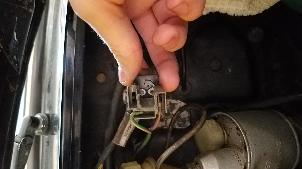 I would but i cant find it. I think its missing the ground wire, in which case i can pretty easily make a new one. Can anyone confirm that its the ground? Both of the other wires connected to it go back to the fuse box if that helps.


